Using Moddable SDK Part 1 (MCP23017, Moddable SDK 5.12.0)
Introduction
This time, I tried using the MCP23017 sample included in the Moddable SDK.
With the release of Moddable SDK 5.12.0, the MCP23017 driver was updated. While one of the contributors of Node-RED MCU was researching the MCP23017, they happened to come across one of my previous articles.
▼ I had previously used the MCP23017 in the following article:
Expanding Microcontroller Pins with an I/O Expander Part 2 (MCP23017)
Info This article is translated from Japanese to English. Introduction Previously, I used an I/O Expander called MCP23S08, but this time, I tried the MCP23017.…
If the Moddable SDK sample runs properly, it should be possible to create a Node-RED node based on it, so I decided to test it first. Along the way, I also updated my Moddable SDK and ESP-IDF environments.
▼ Here are my earlier related posts:
Moddable Twoを使ってみる(Moddable SDK、Node-RED MCU、ESP32)
はじめに 今回はModdable Twoを使ってみました。Moddableが開発したボードで、ESP32とディスプレイが搭載されています。 Node-RED MCUで使っていましたが、Moddable S…
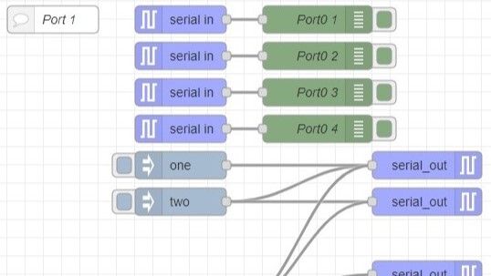
Creating Nodes for Node-RED MCU Part 3 (Serial Node)
Info This article is translated from Japanese to English. Introduction In this post, I created a Serial node for Node-RED MCU. While the debugger tool already …
Setting Up the Environment
Updating Moddable SDK
▼ I followed the instructions on the following page to set up the environment:
https://github.com/Moddable-OpenSource/moddable/blob/public/documentation/Moddable%20SDK%20-%20Getting%20Started.md#win-instructions
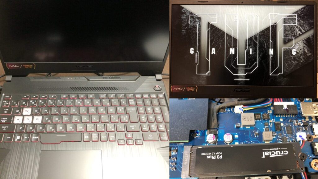
▼ I’m using a gaming laptop that cost around 100,000 yen, running Windows 11.
Shopping: New Laptop and SSD Expansion (ASUS TUF Gaming A15)
Info This article is translated from Japanese to English. Introduction In this post, I’ll be talking about replacing my PC after my previous one broke down. I …

Since I’ve already been using the Moddable SDK for Node-RED MCU, some parts were preinstalled on my system.
▼ The last time I set up the environment was in the following article:
Node-RED MCUの環境を構築する(Moddable SDK 5.4.1、ESP-IDF v5.3.1対応版、Windows 11)
はじめに 今回はNode-RED MCUの環境を構築してみました。 PCを買い替えたので、久々にインストールしました。カメラへの対応も進んでいるようなので、試したいなと思…
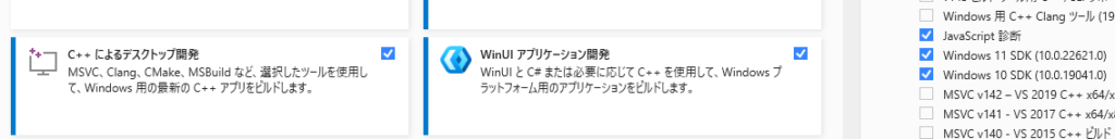
First, I verified that the required components were installed using the Visual Studio Installer.
▼ Under Desktop development with C++, I made sure the Windows 10 SDK (10.0.0.19041.0) was selected.
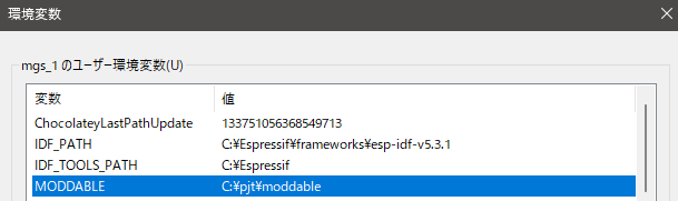
▼ I also confirmed that the MODDABLE environment variable was set correctly.
To update the Moddable SDK, I navigated to the directory and ran the update command:
cd C:\pjt\moddable
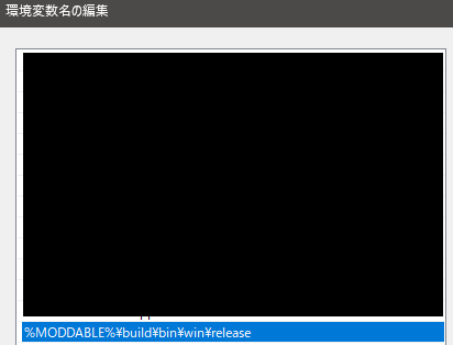
git pull▼ I verified that the path was included in the system Path variable.
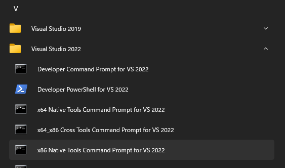
To build, I opened the x86 Native Tools Command Prompt for VS 2022.
▼ This can be found under Visual Studio 2022.
Then, I ran the following commands to build and launch xsbug:
cd %MODDABLE%\build\makefiles\win
build
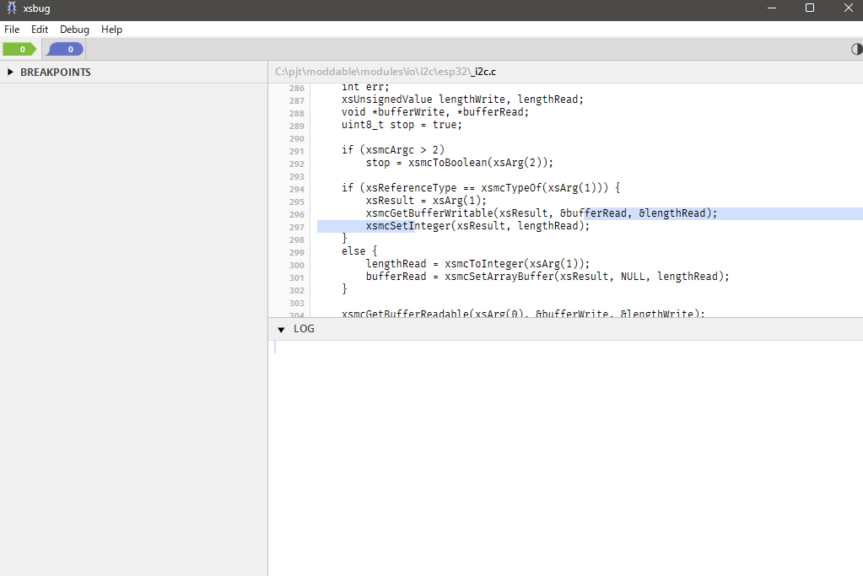
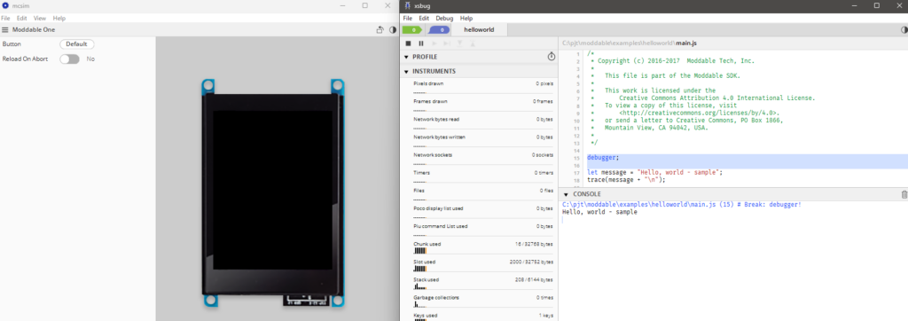
xsbug▼ xsbug launched successfully.
I then ran a sample:
cd %MODDABLE%\examples\helloworld
mcconfig -d -m -p win
▼ The sample executed without issues, and pressing the Start button displayed Hello, world.
Updating ESP-IDF
▼ I followed the instructions here:
https://github.com/Moddable-OpenSource/moddable/blob/public/documentation/devices/esp32.md#win-instructions
Previously, I installed ESP-IDF using an installer, but now the documentation recommends cloning via git.
I cloned version 5.5.1 into my user directory:
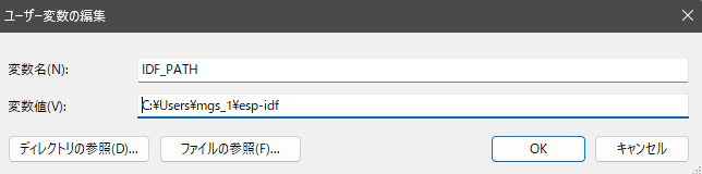
git clone -b v5.5.1 --recursive https://github.com/espressif/esp-idf.gitThen I updated my environment variables accordingly.
▼ Previously, I had configured the environment for version 5.3.1.
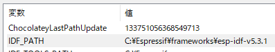
▼ I updated it to point to the newly cloned directory.
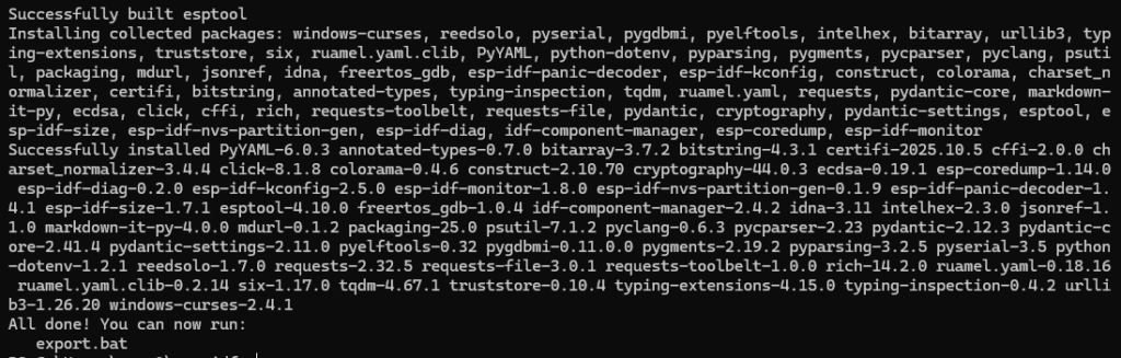
After that, I ran the installation script:
cd esp-idf
install.bat
▼ The installation completed successfully.
Controlling LEDs
Before running the program, I started with the wiring setup.
▼ I purchased the MCP23017 from Akizuki Denshi. A datasheet is also available:
https://akizukidenshi.com/catalog/g/g109486
▼ It’s also available on Amazon, though it’s a bit more expensive there.

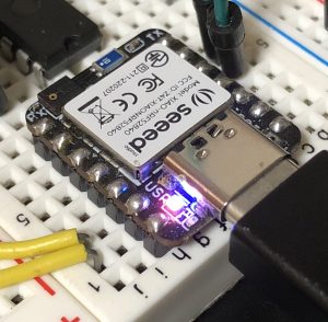
For the microcontroller, I used the Seeed Studio XIAO ESP32C3.
▼ For I2C communication, SDA is on pin 6, and SCL is on pin 7:
https://www.switch-science.com/products/8348

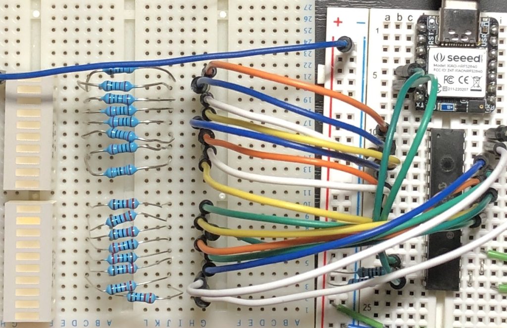
All address pins were connected to GND.
▼ The wiring was done as shown below.
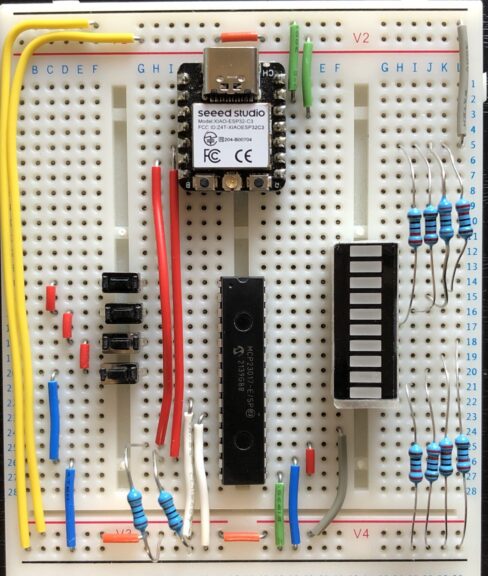
After completing the wiring, I uploaded the program and tested the behavior.
▼ ESP32 flashing instructions can be found here:
https://github.com/Moddable-OpenSource/moddable/blob/public/documentation/devices/esp32.md#win-instructions
▼ The list of supported device names is available here. For the XIAO ESP32C3, use:esp32/xiao_esp32c3
https://github.com/Moddable-OpenSource/moddable/blob/public/documentation/devices/esp32.md#platforms
▼ The MCP23017 sample for Moddable SDK can be found here:
https://github.com/Moddable-OpenSource/moddable/tree/ec3d8103a891127fa0448ddd6dd83c6bdacd57bc/examples/drivers/mcp23017
▼ The documentation was also useful:
https://github.com/Moddable-OpenSource/moddable/blob/ec3d8103a891127fa0448ddd6dd83c6bdacd57bc/documentation/drivers/MCP230XX/MCP230XX.md
I slightly modified the sample code. It was necessary to specify the I2C pins and enable the internal pull-up resistor for the input pin.
Here’s the modified code — it sequentially lights LEDs on pins 0–7, and holding pin 8 pauses the flow.
import Timer from "timer";
import Digital from "pins/digital";
import { MCP23017 } from "MCP230XX";

export default function() {
	const expander = new MCP23017({
		address: 0x20,
		inputs: 0b0000000100000000,
		sda: 6,
		scl: 7,
		pullups: 0b0000000100000000,
	});

	const button = expander[8];  // GPB0 (button input)

	let ports = { a: 0x88, b: 0x00 };
	let indicator = 0;
	let delay = 120;
	let last = Date.now();

	expander.write(0x0000);
	button.mode(Digital.Input);

	Timer.repeat(() => {
		let state = expander.read();
		let buttonPressed = ((state >> 8) & 0x01) === 0;

		if (!buttonPressed) {
			ports.a = ((ports.a << 1) | (ports.a >> 7)) & 0xFF;
		}

		let now = Date.now();
		if (now >= last + delay) {
			last = now;
			if (buttonPressed) {
				indicator ^= 1;
			}
		}

		ports.b = (indicator << 8);
		expander.write(ports.b | ports.a);
	}, 50);
}
To upload to my XIAO ESP32C3 (connected on COM12):
cd %MODDABLE%\examples\drivers\mcp23017
set UPLOAD_PORT=COM12
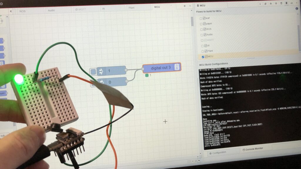
mcconfig -d -m -p esp32/xiao_esp32c3After uploading, I checked it.
▼ It works perfectly. The response is fast.
Conclusion
I confirmed that the MCP23017 works correctly with the Moddable SDK. Later, I also made it compatible with Node-RED MCU, which I’ll cover in a separate article.
Expanding I/O pins with the MCP23017 is convenient, but the code can become a bit complex. Using it through Node-RED MCU should make development much easier.
▼ For more on Node-RED MCU, see the following pages:
書籍紹介:『はじめてのNode-RED』/『はじめてのNode-RED MCU Edition』 - 趣味的ロボット研究所
Node-REDとは 一言でいうと、Node-REDはプログラミングが簡単にできるツールです。ビジュアルプログラミングの一種で、視覚的にわかりやすくなっています。▼百聞は一見に…