Control Motors with Motor Driver Part 1 (TB6612FNG)
Introduction
In this article, I introduce the TB6612FNG, a dual motor driver. I have used it a lot for small robots in the past, but this is an introduction to it again.
It works well with TAMIYA products and I use it to control gearboxes. It would be interesting to use it together with crawlers and tanks of TAMIYA products. I often see examples of production controlled by microcontrollers in books.
In this article, I intend to explain it with production examples, considering that it is easy to understand, especially for beginners in electronic construction. I want to use it to educate new students in club activities…
▼Production example using TB6612FNG

About TB6612FNG
The TB6612FNG is a dual motor driver, meaning it can control two motors.
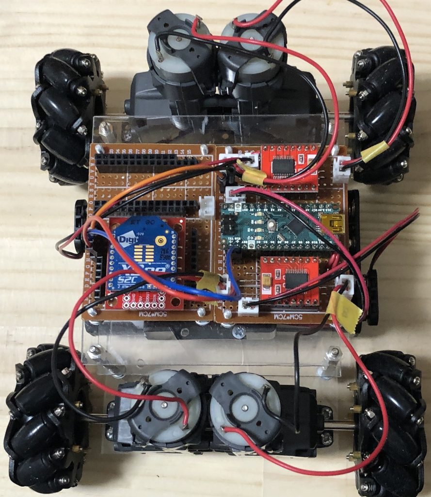
▼For example, I used two TB6612FNG for the Mecanum wheel because it needs to control four tires separately.
Datasheet
You can find out how to use the electronic components by reading the data sheet. It is like an instructions manual.
▼Here is the datasheet. TB6612FNG is made by Toshiba and there is a datasheet in Japanese and other languages.
The first thing I want you to notice is the following three points.
- The power supply voltage in the allowable operating range; with a TAMIYA gearbox and batteries, it should be just fine.
- Never exceed the absolute maximum ratings. The product will break down.
- Control according to the H-SW control function. Refer to this when writing the program.
▼Here is a simplified logic that is common in motor drivers: High and Low are controlled by the program after this.
| IN1 | IN2 | Movement |
|---|---|---|
| High | High | Brake |
| Low | High | Forward rotation |
| High | Low | Reverse rotation |
| Low | Low | Stop |
TB6612FNG controls two motors, A and B. To control A, it looks like the following.
- The operation is controlled by AIN1 and AIN2. Since the high and low of the two pins are controlled, there are four methods.
- PWMA controls the speed.
- Connect the motors to AO1 and AO2.
STBY is the pin to control standby; when low, it goes into standby and the motor cannot run, but the current consumption can be reduced.
Purchase Page
▼Amazon sales page. Be careful because some of them are defective instead of inexpensive.

▼SWITCH SCIENCE sales page. the ones made by Sparkfun are easy to use because the pin names are printed on them.
TB6612FNG搭載 デュアルモータードライバ(ピンヘッダ付き) — スイッチサイエンス
東芝のTB6612FNGを搭載した、連続最大1.2 Aのモーターを2個接続できるモータードライバモジュールです。ピンヘッダ実装済み。

▼Akizuki Denshi's sales page. This is a chip component, so it is difficult to use.
https://akizukidenshi.com/catalog/g/gI-11317/
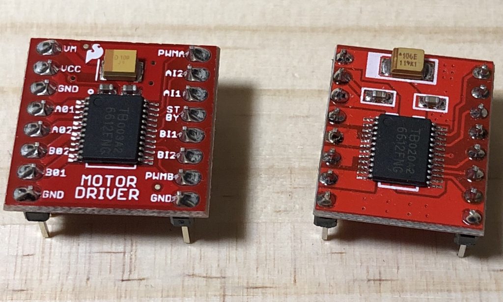
▼The chip components themselves are not much different, but DIP boards that are easier to use with breadboards (see below) may look different from each other.
About Breadboard
▼It is the white board with holes in the picture, where electronic components and wires can be inserted and wired. It is very useful because it allows you to experiment with circuits without soldering.
Build a circuit
In this case, I use an Arduino Uno microcontroller. I won't explain the details of the Arduino, but you can control the voltage on its pins with your program.
Using the digital pins of the Arduino Uno, we will control the High and Low seen in the datasheet; note that some pins can be used for PWM control, while others cannot.
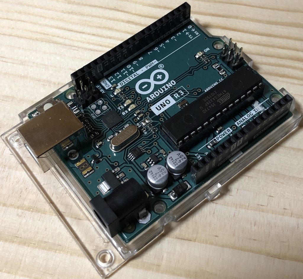
▼Photo of Arduino Uno, pins that can be PWM control are marked with a "~" in the number.
▼The schematic diagram is here. The same symbols are connected to the same pins. In the picture, it is Arduino Nano, but it has the same pin name as Uno.
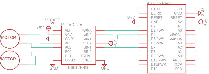
The positive terminal of the AA battery is connected to V_BATT.
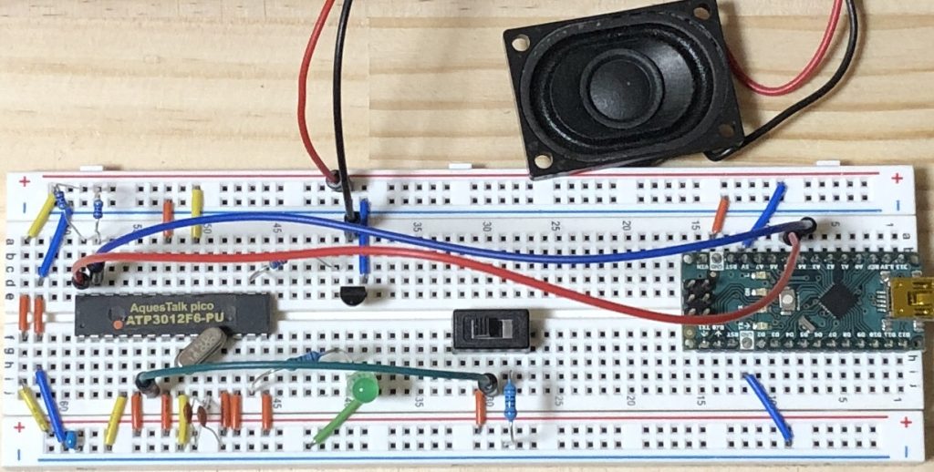
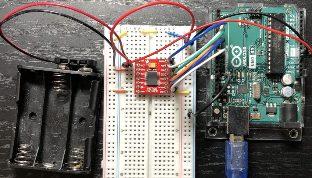
▼A picture of the wiring. It is complicated because the terminals of the motor are also inserted.
Writing Programs
▼program for Arduino
I prepared a very simple Speed() function and Move() function.
Speed() function
The Speed function sets the speed of the two motors with a value from 0 to 255.
analogWrite() can control the average voltage by PWM control.
▼Reference about analogWrite()
https://www.arduino.cc/reference/en/language/functions/analog-io/analogwrite/
Move() function
The switch statement is used to change the operation depending on the argument. The loop statement is used to obtain the value input to the serial monitor and control the motor to that value.
Control motors
I changed Speed() and checked the operation.
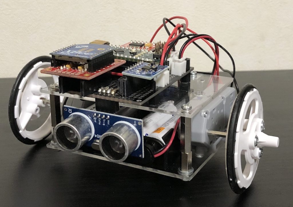
I used TAMIYA's "Mini Motor Thin Gearbox" which is attached to the two-wheeled robot I made before.
▼Speed(255). It is quite fast when running actually.
▼Speed(100). This is about the right speed to control with a controller.
Finally
TB6612FNG is very easy to use and highly recommended. There are other motor drivers available, and I think they can be controlled in the same way because the way to use them is similar.
▼In my previous article, I was also able to control a stepping motor using TB6612FNG. DRV8833 is another commonly used motor driver.
Control Stepping Motors with Motor Drivers (DRV8833, TB6612FNG)
Introduction In this article, I controlled a stepping motor with motor drivers. It is a bipolar type of stepping motor. When I looked for a module for steppi…