Trying Out Distance Sensors Part 1 (VL53L0X)
Introduction
In this post, I experimented with the VL53L0X distance sensor. This sensor is also used in "RumiCar," an autonomous driving algorithm development platform.
▼Here is the RumiCar repository:
https://github.com/RumiCar-group/RumiCar
In the repository photos, you can see three VL53L0X sensors mounted on the front of the vehicle.
▼I found an article by someone building a RumiCar. It seems that when using multiple VL53L0X sensors, the XSHUT pin is required.
https://elchika.com/article/0b3028f8-6417-4f0e-8359-be417aab77f4/
▼Regarding the "RumiCar-C3" currently under construction:
https://protopedia.net/prototype/5030
▼Now, the question is how to mount the sensors…


Overview
▼Here is the product page at Akizuki Denshi. I purchased one there, but for this project, I'm using a unit I bought on Amazon.
https://akizukidenshi.com/catalog/g/g112590/

▼The official STMicroelectronics page:
https://www.st.com/ja/imaging-and-photonics-solutions/vl53l0x.html
According to the datasheet, it uses a Class 1 laser. The Field of View (FoV) is 25° for the collector and 35° for the emitter. Since the measurement range is crucial for design, I will verify this later.
The sensor communicates via I2C, and the address can be changed via software.
Building the Circuit
I am using the XIAO ESP32C3 as the microcontroller.
▼The product page for the XIAO ESP32C3 is here:
https://akizukidenshi.com/catalog/g/g117454
Seeed Studio XIAO ESP32C3 — スイッチサイエンス
Bluetooth Low EnergyとWi-Fiを搭載した小型マイコンボードです。IoTや携帯するアプリケーションに最適です。工事設計認証を取得しています。


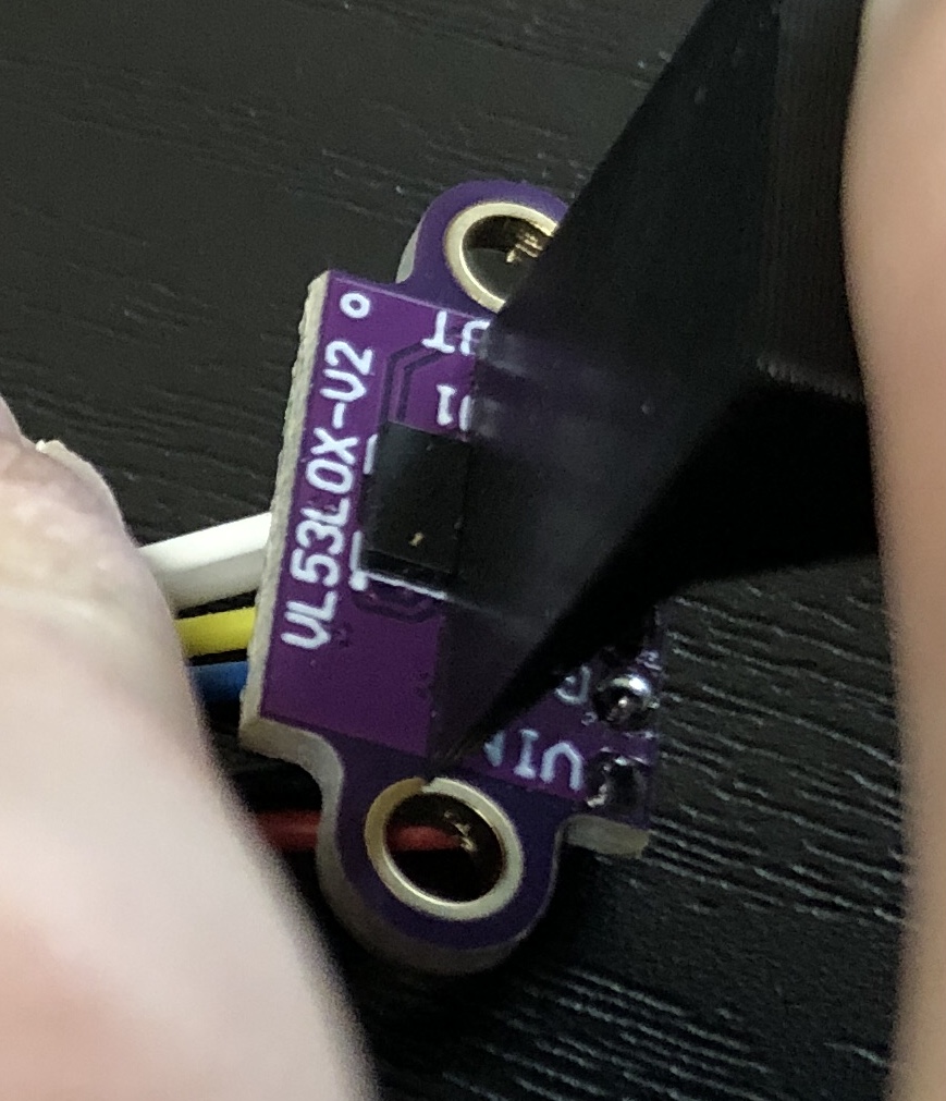
▼I wired it as follows, connecting the I2C pins and the XSHUT pin.

▼Wired using jumper wires:

Writing the Program
Testing Sample Programs
First, let's try a sample program.
▼I'm using the library available via the Arduino IDE Library Manager:
https://github.com/pololu/vl53l0x-arduino
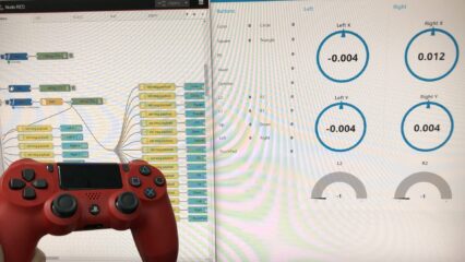
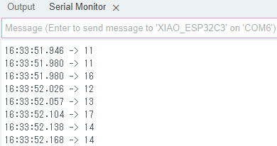
▼The Serial Monitor while running the "Continuous" example. The numbers change according to the distance.
While designing the chassis, I was curious about the detection angle range. It seems the laser travels in a fairly straight line.
▼When placing a board in front of it, it responded within this specific angle:
Changing the I2C Address
Since I plan to use three sensors later, I need to be able to change the address. First, I checked the current address using an I2C Scanner.
▼The I2C Scanner, also introduced here:
https://playground.arduino.cc/Main/I2cScanner/
#include <Wire.h>
void setup() {
Wire.begin();
Serial.begin(9600);
Serial.println("\nI2C Scanner");
}
void loop() {
byte error, address;
int nDevices;
Serial.println("Scanning...");
nDevices = 0;
for (address = 1; address < 127; address++) {
Wire.beginTransmission(address);
error = Wire.endTransmission();
if (error == 0) {
Serial.print("I2C device found at address 0x");
if (address < 16)
Serial.print("0");
Serial.print(address, HEX);
Serial.println(" !");
nDevices++;
} else if (error == 4) {
Serial.print("Unknown error at address 0x");
if (address < 16)
Serial.print("0");
Serial.println(address, HEX);
}
}
if (nDevices == 0)
Serial.println("No I2C devices found\n");
else
Serial.println("done\n");
delay(5000); // wait 5 seconds for next scan
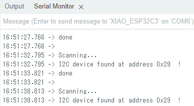
}▼The current address appears to be 0x29.
Now, let's change the address.
▼Using the setAddress function from the library:
https://github.com/pololu/vl53l0x-arduino#:~:text=void%20setAddress(uint8_t%20new_addr)
▼Here is the combined program. I'm setting the address to 0x30.
#include <Wire.h>
#include <VL53L0X.h>
VL53L0X sensor;

void setup() {
  Serial.begin(9600);
  Wire.begin();

  sensor.setTimeout(500);
  if (!sensor.init()) {
    Serial.println("Failed to detect and initialize sensor!");
  }
  sensor.startContinuous(100);
  sensor.setAddress(0x30);
}

void loop() {
  byte error, address;
  Serial.print(sensor.readRangeContinuousMillimeters());
  if (sensor.timeoutOccurred()) { Serial.print(" TIMEOUT"); }

  Serial.println();

  for (address = 1; address < 127; address++) {
    Wire.beginTransmission(address);
    error = Wire.endTransmission();

    if (error == 0) {
      Serial.print("I2C device found at address 0x");
      if (address < 16)
        Serial.print("0");
      Serial.print(address, HEX);
      Serial.println("  !");
    } else if (error == 4) {
      Serial.print("Unknown error at address 0x");
      if (address < 16)
        Serial.print("0");
      Serial.println(address, HEX);
    }
  }
}
▼The address has been successfully changed to 0x30.
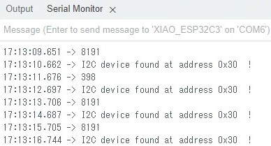
Using the XSHUT Pin
When the XSHUT pin (connected to D10) is set to LOW, the sensor enters a reset state and stops operating. This is how we can change the addresses of multiple sensors individually.
I wrote a program to keep XSHUT LOW initially, then set it to HIGH before assigning the address. Interestingly, if I tried to run init() immediately after setting the pin to HIGH, the initialization failed. Adding a delay(10) solved the problem, so it seems to be a timing issue.
▼The program:
#include <Wire.h>
#include <VL53L0X.h>
VL53L0X sensor;
const int XSHUT1 = D10;

void i2c_scan() {
  byte error, address;
  for (address = 1; address < 127; address++) {
    Wire.beginTransmission(address);
    error = Wire.endTransmission();

    if (error == 0) {
      Serial.print("I2C device found at address 0x");
      if (address < 16)
        Serial.print("0");
      Serial.print(address, HEX);
      Serial.println("  !");
    } else if (error == 4) {
      Serial.print("Unknown error at address 0x");
      if (address < 16)
        Serial.print("0");
      Serial.println(address, HEX);
    }
  }
}

void setup() {
  Serial.begin(9600);
  Wire.begin();

  pinMode(XSHUT1, OUTPUT);
  digitalWrite(XSHUT1, LOW);
  delay(1000);
  i2c_scan();

  digitalWrite(XSHUT1, HIGH);
  // これが無いと初期化に失敗する!
  delay(10);
  if (!sensor.init()) {
    Serial.println("Failed to detect and initialize sensor!");
  }
  sensor.setTimeout(500);
  sensor.startContinuous(10);
  sensor.setAddress(0x30);
  i2c_scan();
}

void loop() {
  Serial.println(sensor.readRangeContinuousMillimeters());
  if (sensor.timeoutOccurred()) { Serial.println(" TIMEOUT"); }
}
Finally
Now that I understand the general measurement range and how to change the addresses, I can incorporate this into the design of RumiCar-C3. My current challenge is figuring out how to fit everything in...
The ability to freely set addresses via software is quite interesting. Depending on the application, I wonder if it’s possible to mount a massive number of these sensors.