Trying Out Unreal Engine 5 Part 7 (Open Manipulator)
Introduction
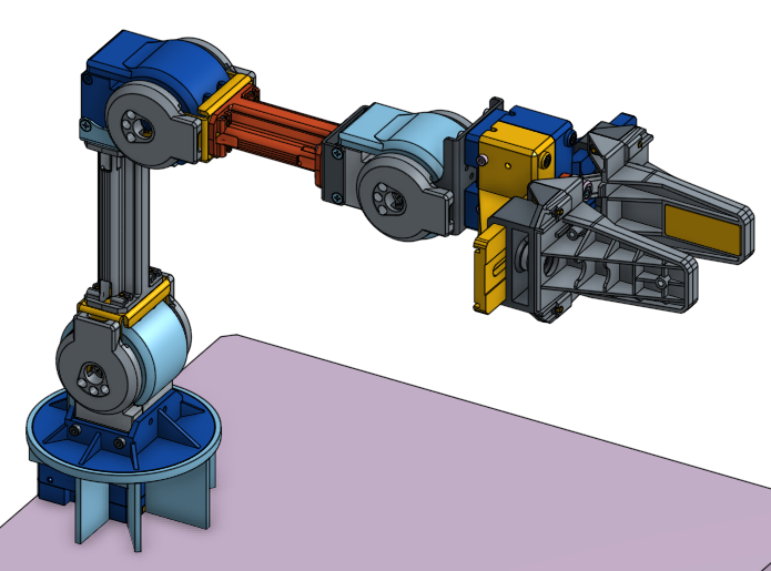
In the previous post, I created a basic robotic arm in Unreal Engine 5 (UE5). This time, I’ve created a model for the "Open Manipulator," a robotic arm released as open source by ROBOTIS. I have also created models for robotic arms from specific companies, but I don't publish those due to potential licensing issues. In that regard, the open-source nature of this project is very helpful. Since I have borrowed the actual Open Manipulator hardware, I hope to reflect its real-world movements in the simulation eventually.
▼The project is labeled as OpenSoftware and OpenHardware. STL files are publicly available.
https://wiki.ros.org/open_manipulator
▼The GitHub repository is under the Apache-2.0 license.
https://github.com/ROBOTIS-GIT/open_manipulator
▼Previous articles:
Trying Out Unreal Engine 5 Part 4 (Unreal Learning Kit: Training Virtual Robots – Lesson 1)
Info This article is translated from Japanese to English. Introduction I recently tried out a virtual robot tutorial available in Unreal Engine 5. This is my f…
Trying Out Unreal Engine 5 Part 6 (Robotic Arm and Blueprints)
Info This article is translated from Japanese to English. Introduction In this post, I tried creating something like a robotic arm in Unreal Engine 5 (UE5). It…
Creating the 3D Model
Importing CAD Data
The CAD data found on GrabCAD was in STEP format, which I could import using DataSmith as shown in a previous article.
▼GrabCAD data link:
https://grabcad.com/library/openmanipulator-x-frame-set-rm-x52-1
This time, I will import data in STL format. Since DataSmith doesn't seem to support direct STL imports, I’ll convert it using Blender first.
Any software that can import STL and export to other formats should work. I’ve successfully used Fusion 360 for this as well.
▼There are also web-based converters for STL to FBX.
https://products.aspose.app/3d/jp/conversion/stl-to-fbx
▼Blender download page:

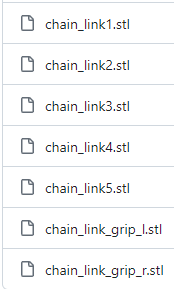
▼For the Open Manipulator data, I used the seven mesh files from the GitHub repository:
https://github.com/ROBOTIS-GIT/open_manipulator/tree/master/open_manipulator_description/meshes
▼Detailed assembly data (including screws) can be found here, though I won't go into that much detail this time:
Let's import it into Blender and convert it.
▼Import in STL format.
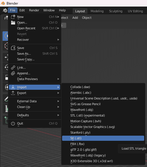
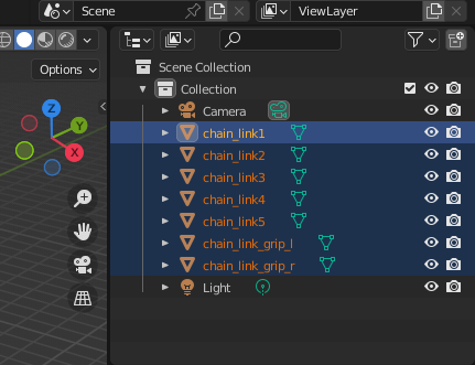
The files are added to the Collection in the top right. Select the necessary parts and export.
▼The interface looks quite similar to Unreal Engine.
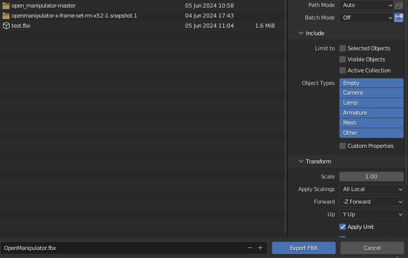
▼Export in FBX format. This format can be imported directly into Unreal Engine.
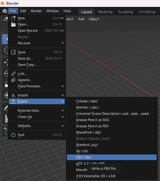
▼Settings can be adjusted right before exporting.
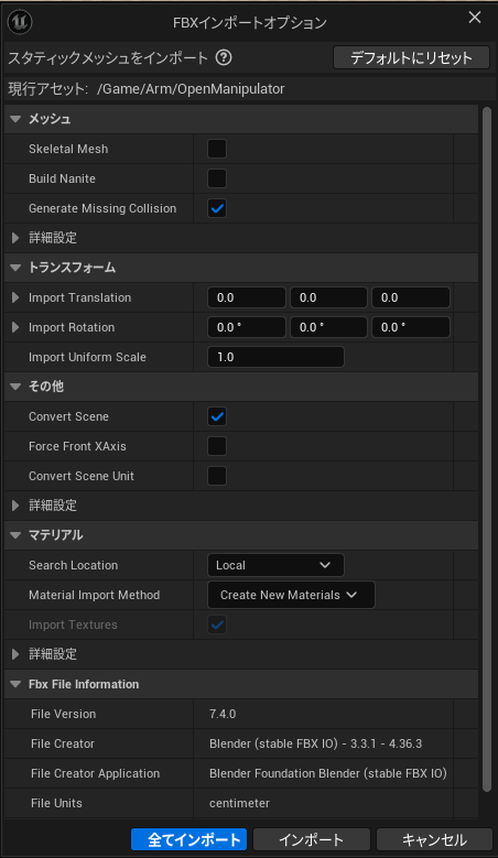
Once exported, bring the file into the Content Drawer.
▼An options window appears before importing.
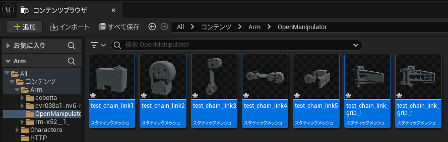
▼Imported successfully!
I tried placing the imported data directly, but it resulted in a massive object.
▼The tiny objects visible at the bottom left are the Third Person Character and others.
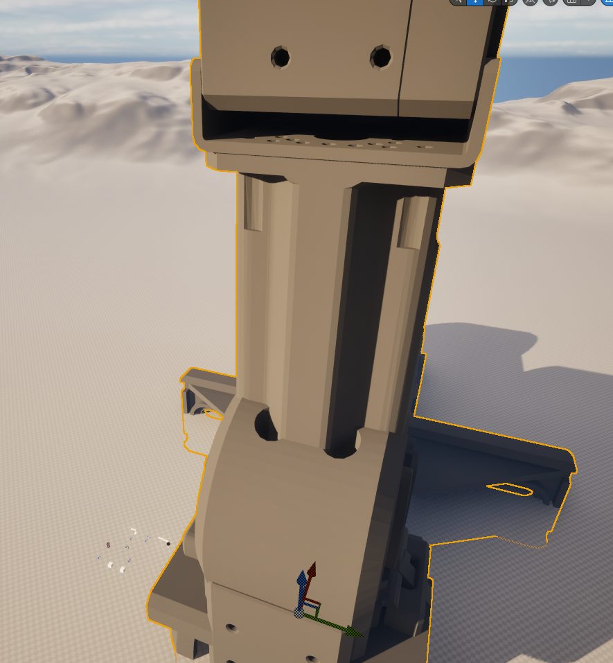
It seems Blender and Unreal Engine use different units.
▼I found information regarding this:
https://qiita.com/ishiitakeru/items/2adc260d71a6b0a2c640
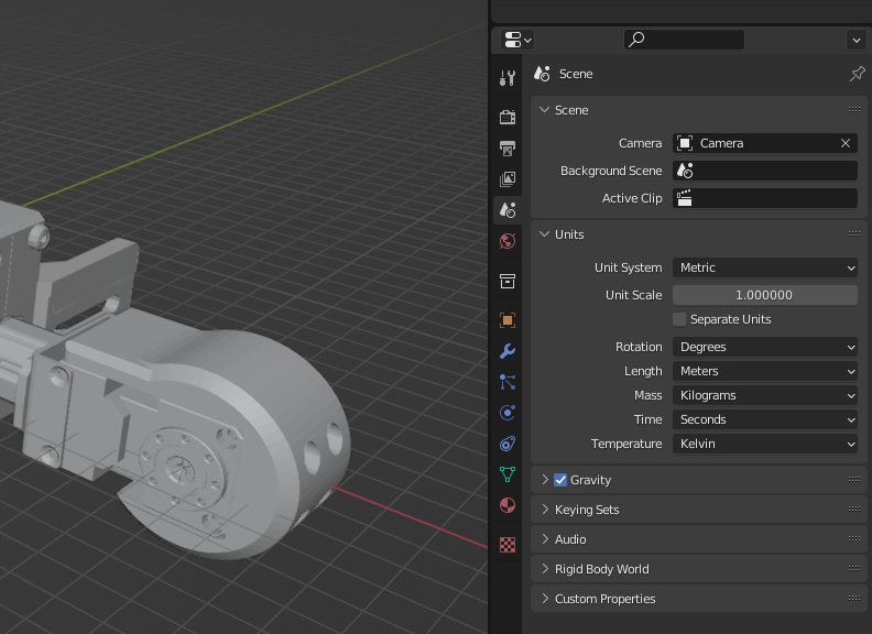
The unit system in Blender's right-side settings panel shows "Metric" (meters).
▼The unit system is Metric.
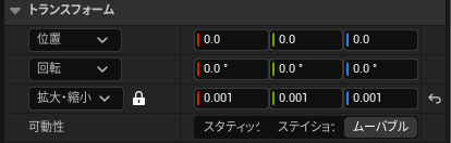
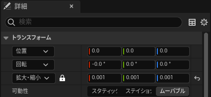
In Unreal Engine, I adjusted the scale in the Transform settings.
▼A scale of 0.001 seemed just right.
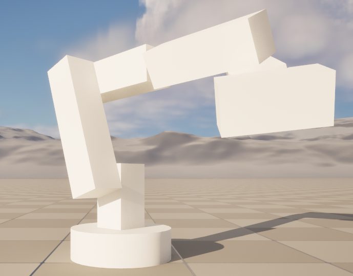
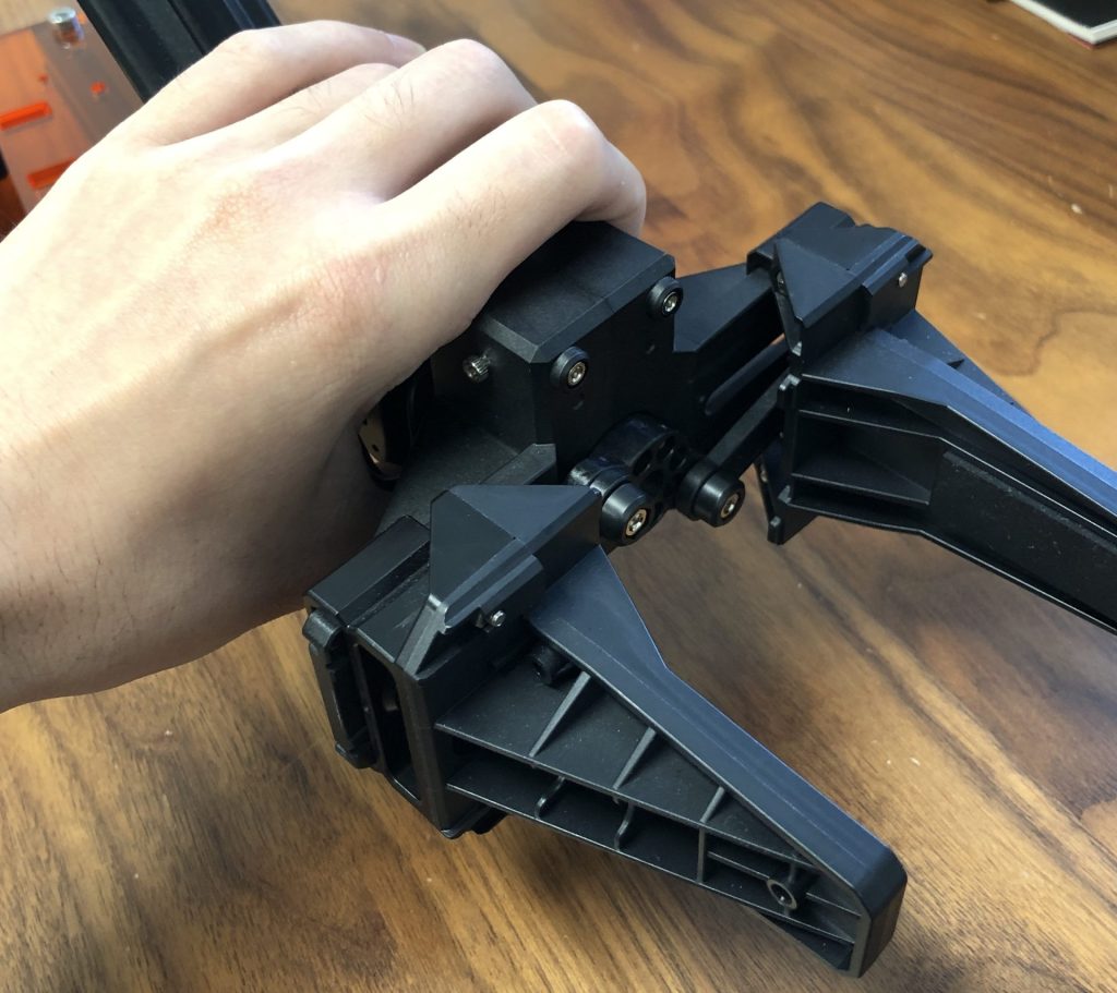
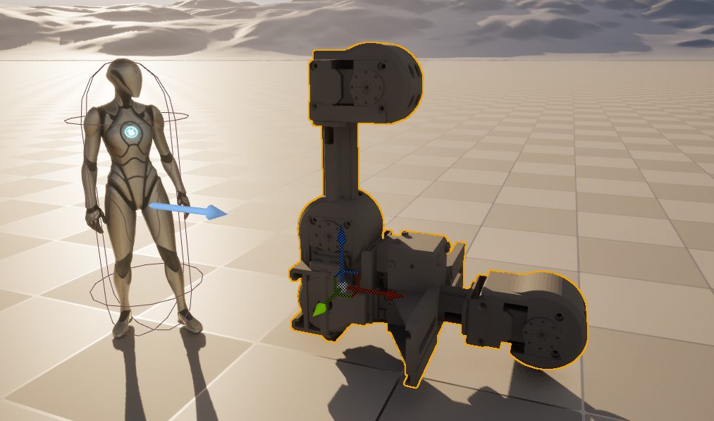
▼This is how large it looks relative to a human hand.
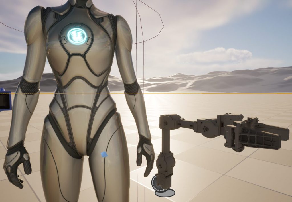
▼Comparison with data imported via GrabCAD. They are roughly the same.
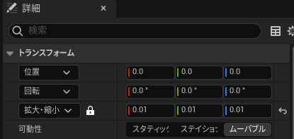
▼For reference, a scale of 0.01 makes it about the size of a person.
Creating the Blueprint Class
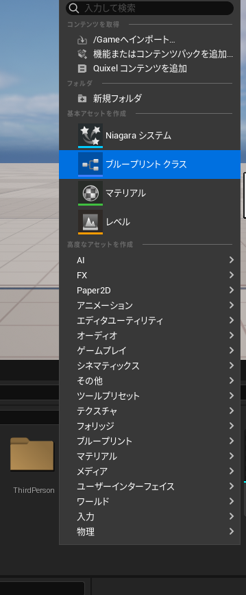
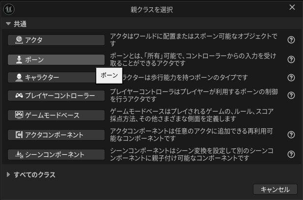
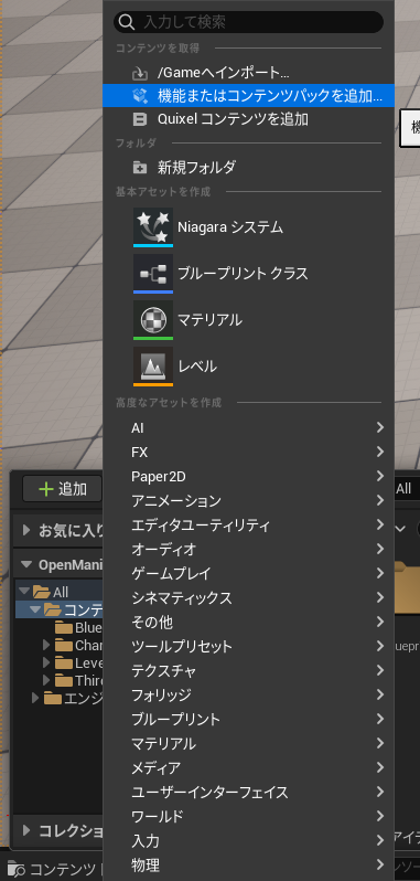
I’ll create this as a Pawn Blueprint class.
▼Right-click in the Content Drawer to create a Blueprint Class.
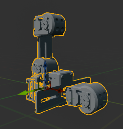
Next, add the imported CAD data.
▼By default, they are all clustered at the center.
▼You can use the Transform settings in the Details tab here as well.
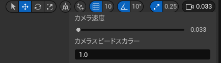
▼The parts are small and can be hard to manipulate, so I recommend lowering the camera speed.
Placing Components
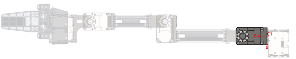
When placing the parts, I named the rotation axes and joints according to the Open Manipulator documentation.
▼Open Manipulator Inertia specification page:
https://emanual.robotis.com/docs/en/platform/openmanipulator_x/specification/#inertia
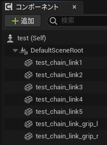
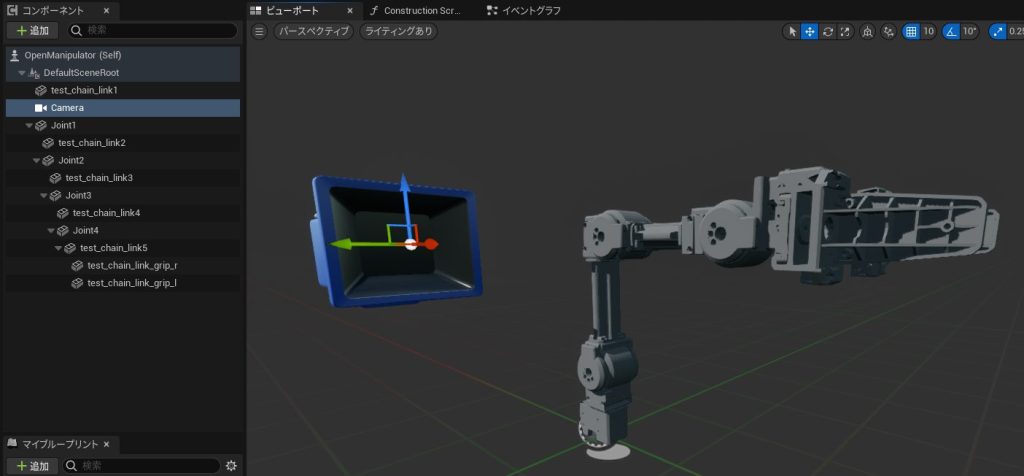
▼After importing the data, the hierarchy looks like this.
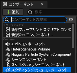
I added "Joint1" through "Joint4" here.
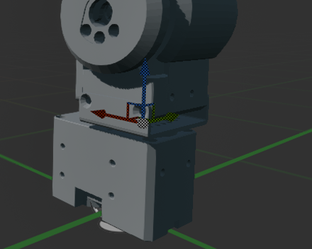
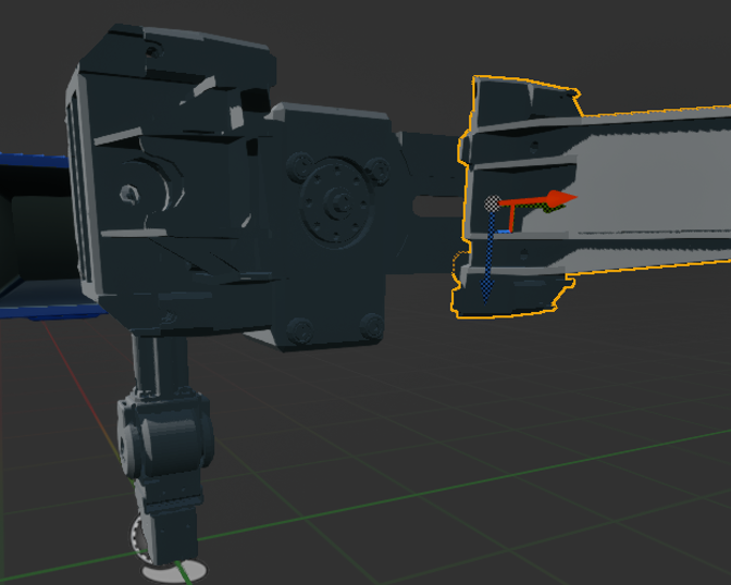
▼Add Static Mesh components to act as Joint1–4. These will serve as the rotation axes.
From the base, we have "test_chain_link1" to "5," and the gripper parts "test_chain_link_grip_r/l." I set up parent-child relationships so that moving a base part moves the subsequent hand parts with it.
▼The hierarchy is set up as follows.
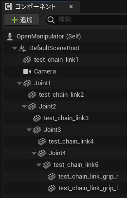
I configured the placement and relative positions for each joint, starting from the base. Moving a parent element later will shift all its children.
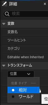
▼You can verify relative vs. world coordinates in the Transform section.
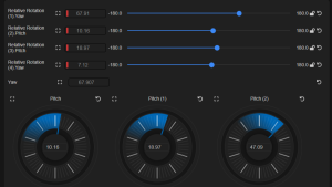
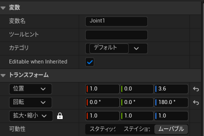
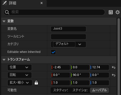
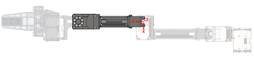
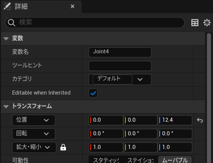
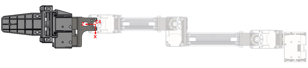
Here are the parameters, joint positions, and axis settings based on the documentation (note: there might be slight offsets).
▼Joint 1 details
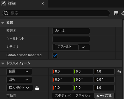
▼Joint 2 details
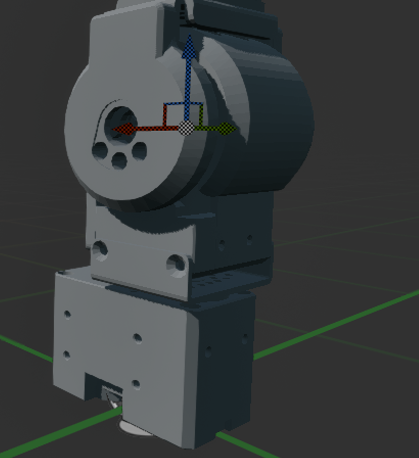
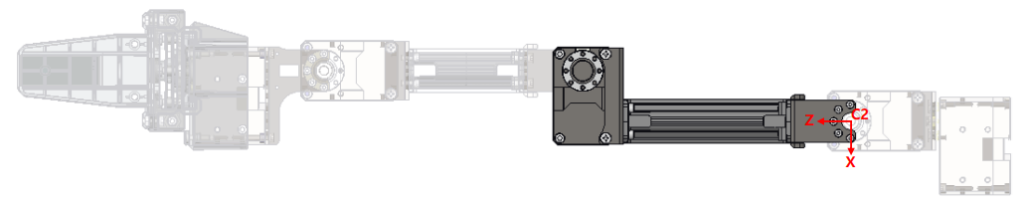
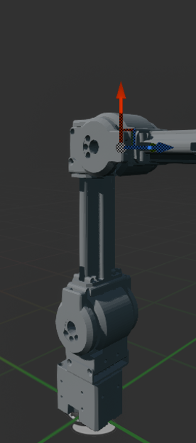
▼Joint 3 details
▼Joint 4 details
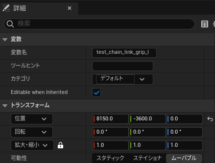
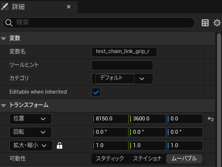
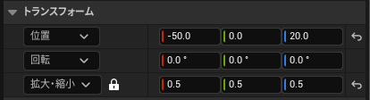
Components that are children of a Joint have their relative positions set to 0 for all axes. The Grip, however, requires adjustment.
▼Grip parameters are as follows.
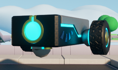
Finally, since the camera becomes active when possessed as a Pawn, I placed it in a good viewing position.
▼Completed view.
▼I scaled down the camera model because it was large, though it doesn't seem to affect the field of view.
Creating the Blueprint
Variable Setup
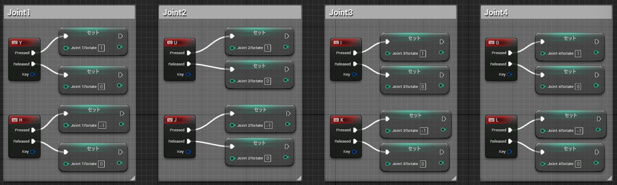
The operation of the rotation axes is almost identical to the previous article. I mapped the keyboard keys to match the official Open Manipulator keyboard teleoperation layout.
▼Mapped according to the Keyboard Teleoperation guide:
▼Assigned keys:
y : increase joint 1 angle
h : decrease joint 1 angle
u : increase joint 2 angle
j : decrease joint 2 angle
i : increase joint 3 angle
k : decrease joint 3 angle
o : increase joint 4 angle
l : decrease joint 4 angle
g : gripper open
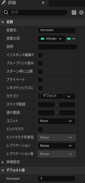
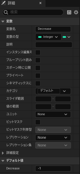
f : gripper close▼Defined variables are as follows. I'll also make the camera operable later.
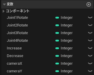
▼Increase and Decrease are assigned default values of 1 and -1.
▼Inputting Joint keys saves the state into variables.
Rotation Settings
Unlike the previous article, I changed the node used for rotation. Previously, I used "Add Relative Rotation," but it sometimes exhibited strange behavior.
▼As seen in the video, it sometimes vibrated instead of rotating properly.
Researching this, I found that there are different nodes for World, Local, and Relative rotation.
▼This was discussed here. It's easy to understand with the GIF.
Relative Rotation rotates based on the local axis of the parent. I switched to "Add Local Rotation" to ensure smooth movement.
▼Logic uses "Branch" nodes to transition to the next check regardless of whether the result is True or False.
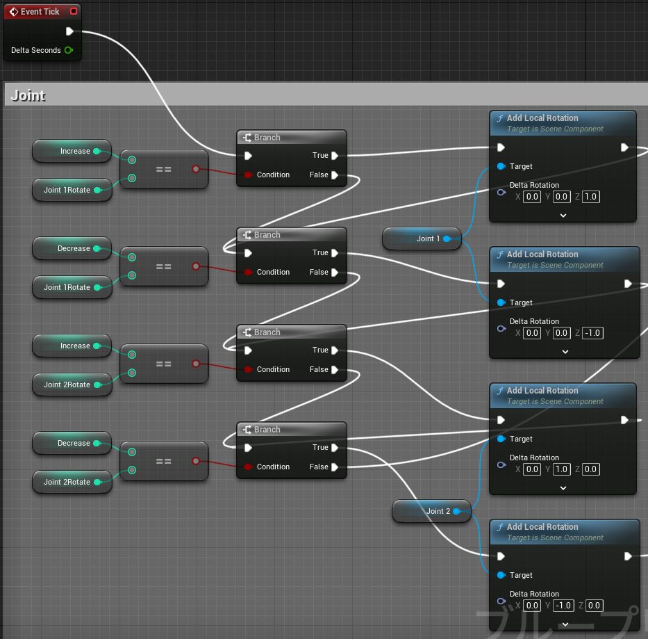
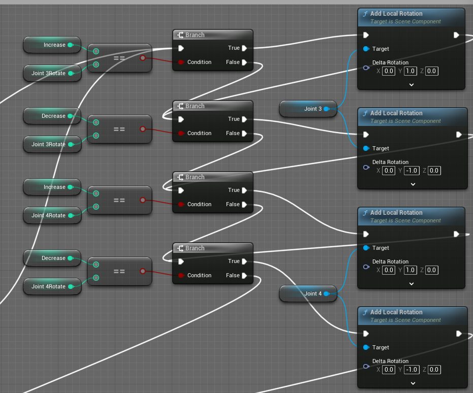
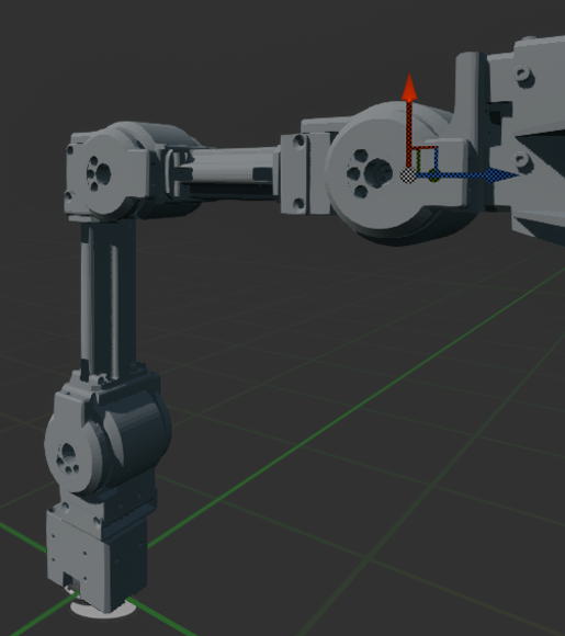
▼If the axis assignments are correct, it moves like this.
Gripper Open/Close
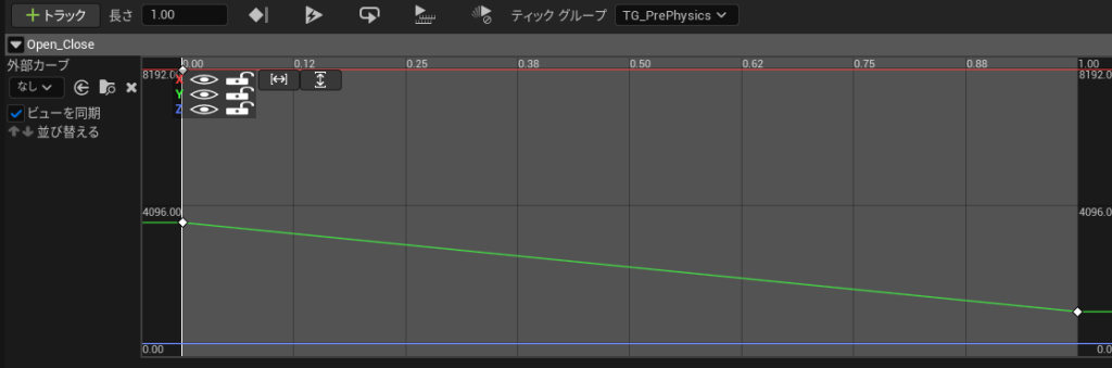
In addition to rotation, I needed the gripper to open and close. I implemented this using a "Timeline" node and "Set Relative Location."
▼Node structure: I multiplied by -1 for one side because the right and left grips move in opposite directions along the Y-axis.
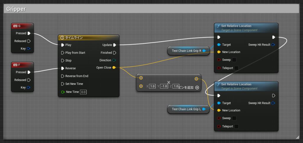
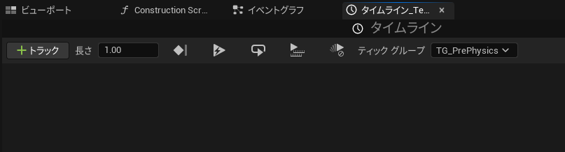
The Timeline node is set to "Play" to open and "Reverse" to close. Double-clicking it opens the editor.
▼When you open it, there's nothing there yet.
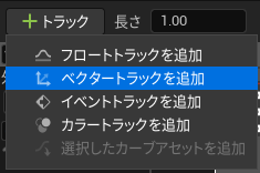
▼Add a Vector Track.
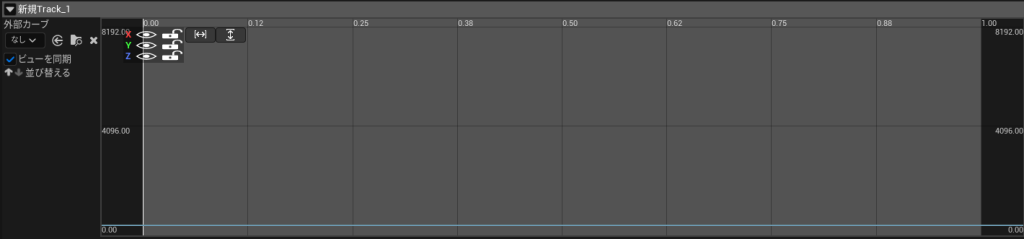
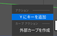
▼Right-click the colored line to add keys.
Based on the relative position of the Grip, I adjusted the parameters (only the Y-axis changes):
- X: Constant at 8150
- Y: 3600 at 0s, 950 at 1s
- Z: Constant at 0
▼The UI allows you to auto-fit the view to the curve.
Camera Movement
I also made the camera position movable using "Add Relative Location," following the same logic as the joints.
▼WASD keys for forward/backward/left/right movement.
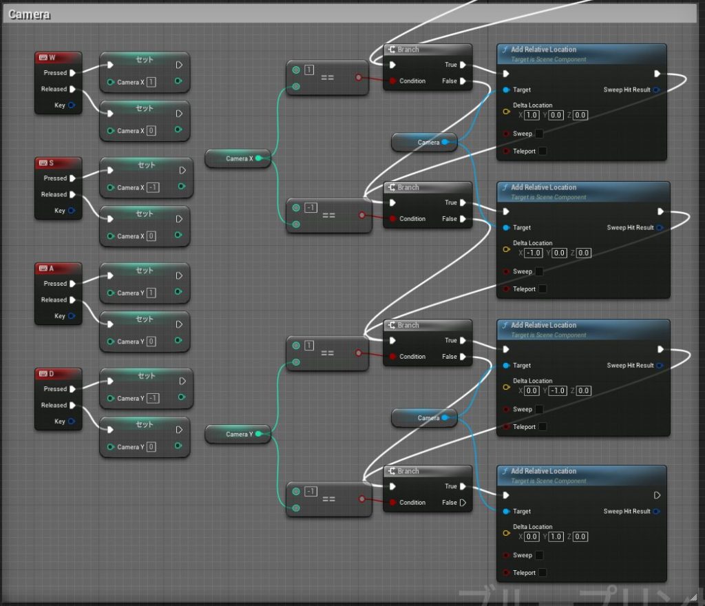
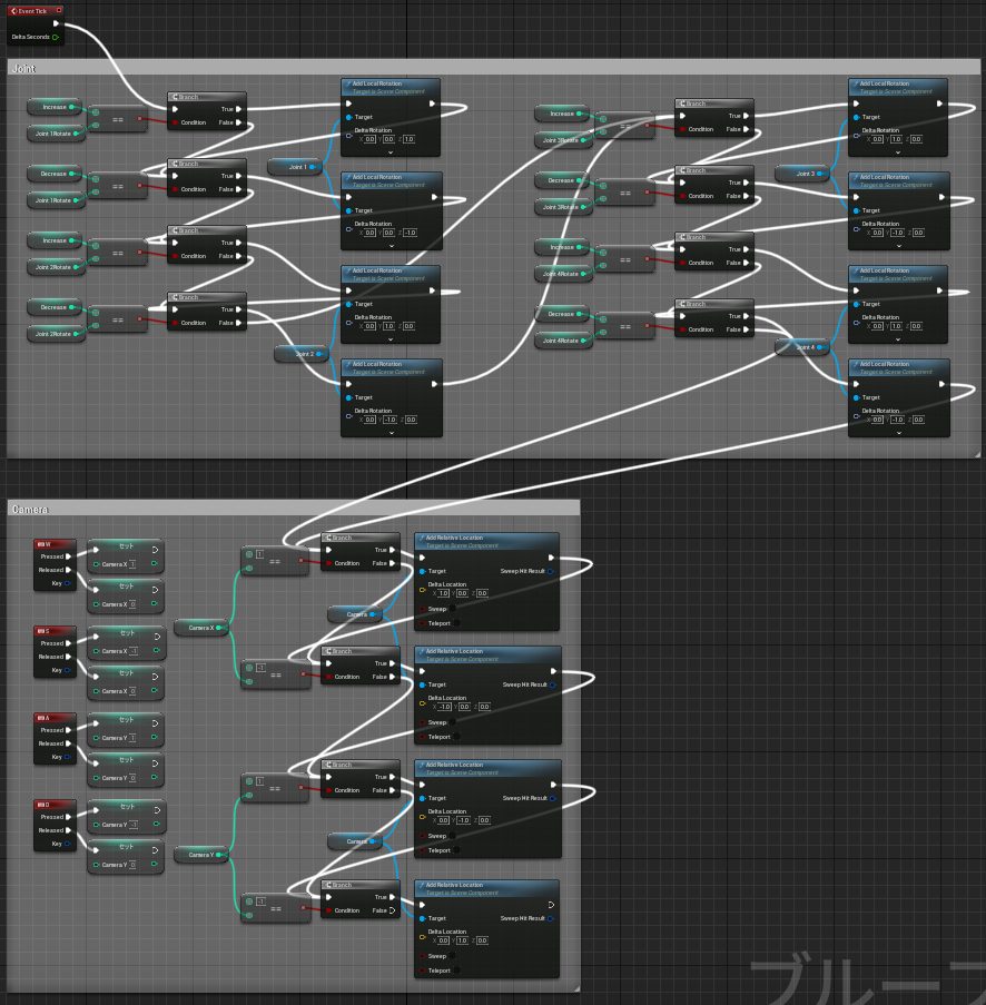
▼The camera branches are connected after the joint branches. Here is the overall view.
Placing in Level and Testing
Possessing the Pawn Class
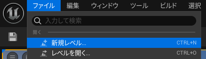
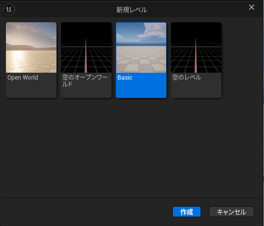
I created a new "Basic" level.
▼Created via New Level.
▼I placed three Open Manipulators and one Third Person Character.
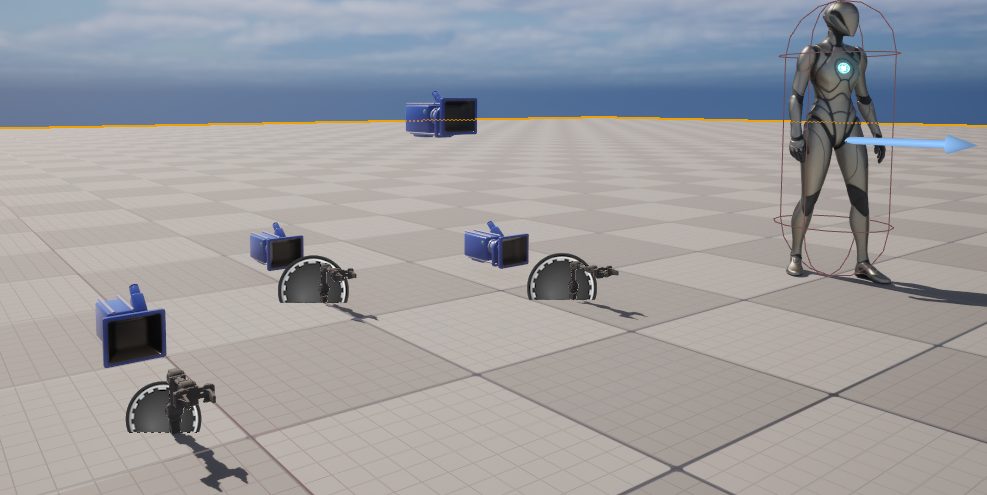
▼The Third Person Character is mainly for size comparison.
Since these are Pawn classes, they must be "possessed" to be operated.
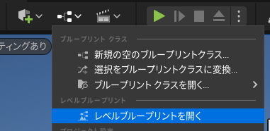
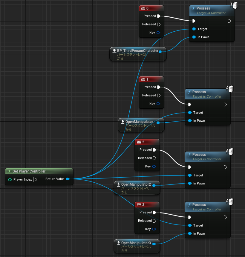
▼Added to the Level Blueprint.
▼Each can be possessed by pressing the corresponding number on the keyboard.
Testing
▼I possessed each Pawn class and moved them. The camera is also adjustable.
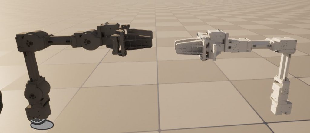
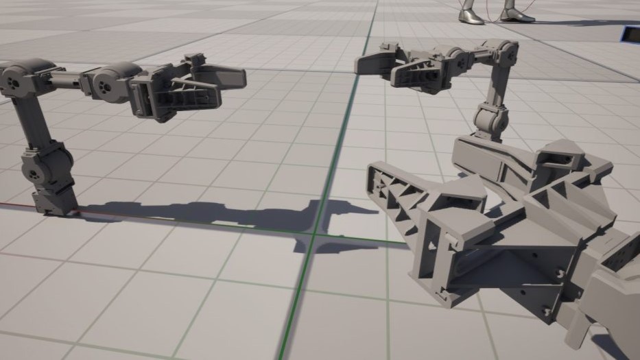
▼Rearranged them for a "chatting" look.
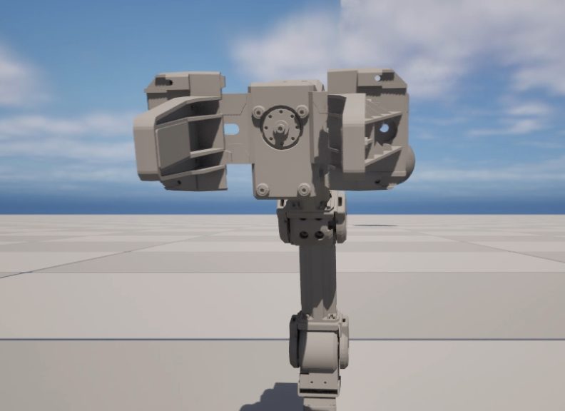
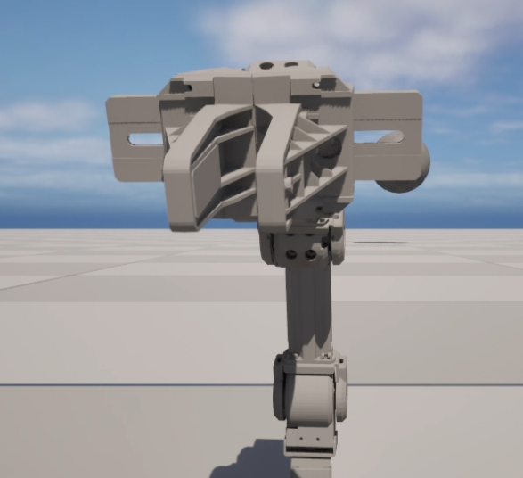
▼Gripper open/close is working.
Finally
It looks much more like a real robotic arm compared to the cube-only model. I want to continue refining its performance.
Compared to the Third Person Character, it seems like a reasonable size, though it's hard to tell. Maybe it would look more substantial if the camera were closer.
This time I only programmed joint rotation and gripper movement, so I want to add collision settings and Pose settings for ROS control next. Multi-player or AI-driven operation could also be interesting.
I've heard that calculations become difficult as the number of axes increases, so I might not be able to handle all formulas within UE5 alone. I hope to solve that by linking it with external programs via Node-RED.